Overview of the framework
The approach we are taking to creating an extensible system is to encapsulate the state of the system, insofar as possible, in a single data structure. Actions required to build a new extension, such as putting buttons and images on the screen, and storing intermediate results, are done by changing this data structure; changes are automatically reflected on the display. The advantage of this approach is that, instead of needing to learn a complex set of APIs for drawing and placing interactive controls, the extender just needs to know the operations on this data structure.Specifically, the state is represented by a tree in which nodes are labelled with names and attributes. The tree structure represents both logical containment (e.g. pages within a lecture) and physical containment (e.g. buttons within a panel). In this tree, for example, an ink stroke is represented by a node labelled "Stroke" with an attribute consisting of a sequence of (x,y) locations. The structure of the tree is largely unconstrained. In particular, although some node names are reserved for special purposes, the user can otherwise create new nodes and attributes at will. Because such trees have a natural external representation as XML trees, we sometimes refer to our system as being "XML-based." In practice, we do not use the built-in XML "DOM" model for the internal representation of trees.
The job of the "core" system is to interpret, and act upon, this tree. The structure of the tree must conform to these rules (among others, but we will get into details in the next section): The root node is labeled "Slice" and has one child labeled "Frames", which in turn has some number of children each labeled "Frame". Each Frame node has an attribute DisplayId with value, say, "mydisplay"; somewhere in the tree there must be a node with the "Id" attribute having value "mydisplay". The latter is the node containing the items that are currently displayed in that frame. Within that node, all children are displayed, as follows: If the node is named Button, TextBox, Label, Image, or Stroke, then the node is displayed on the screen in the obvious way; if not, then all the node's children are recursively displayed.
For example, this tree
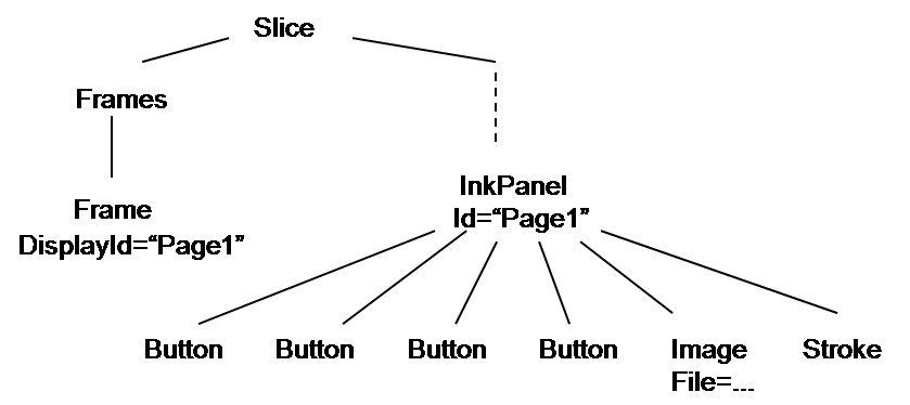
might (when all the details are filled in) correspond to a screen like this:

where the underlying slide is the image, the "Cool" is the ink stroke, and the four buttons on top correspond to the Button nodes.
To complete this overview, we need to explain how locations of items on the screen are given, and then how scripts are incorporated into the tree, and what they do. Again, full details are given in the next section.
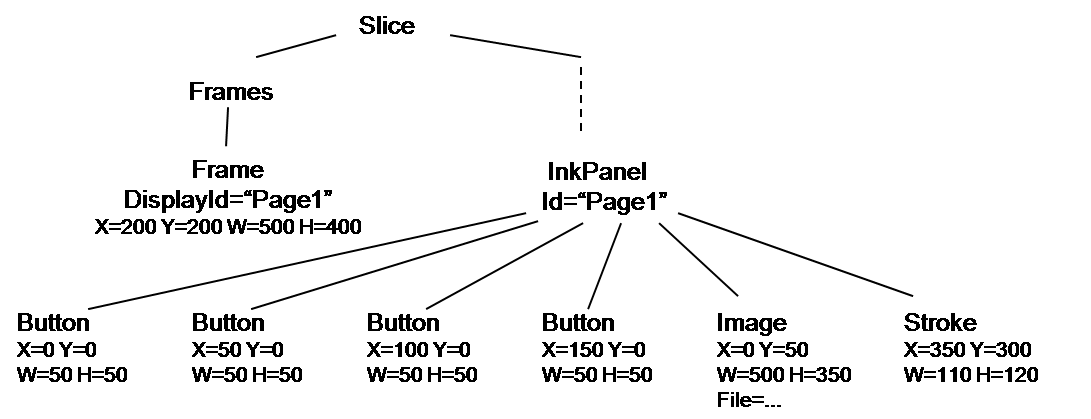
The size and location of each object in the tree is given explicitly. Each node gives this information, in pixel units, using attributes W and H (for width and height) and X and Y (for location of upper-left corner). Thus, a Frame with attributes W=500, H=400, X=0, and Y=200 will create a 500x400 pixel frame on the screen, hugging the left size and 200 pixels down. Thus, the tree above might be
"Container" nodes establish their own coordinate systems in which the upper-left corner is location (0,0). There are two types of container nodes: Panel and InkPanel. Both can contain buttons, labels, etc., but only InkPanels can contain ink strokes. Sizes are always given in pixels. As an example, the tree
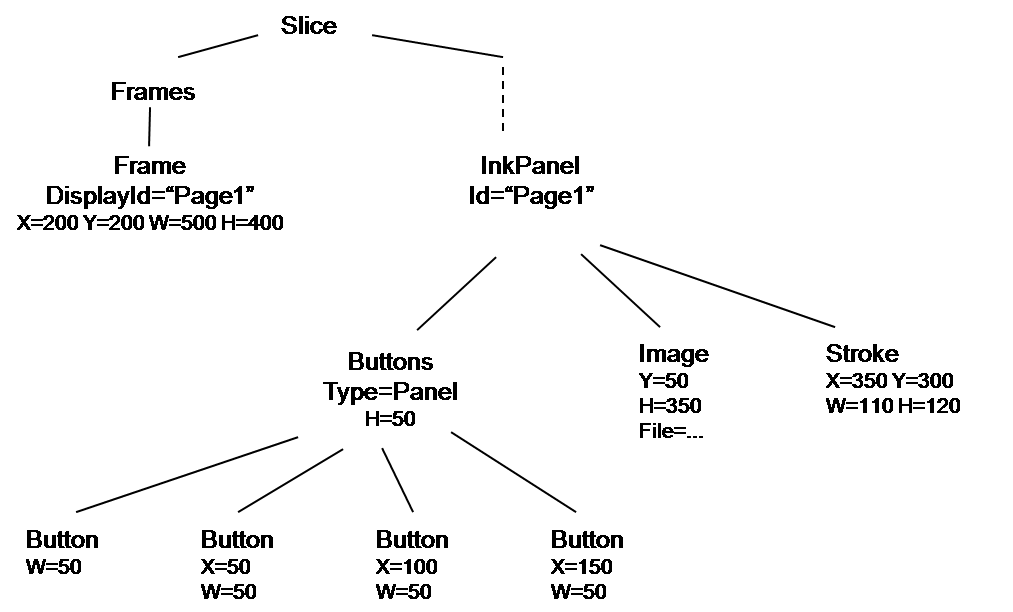
would produce the same screen image as the one above. Here we have followed the convention of omitting attributes when they take their default values - 0 for X or Y, the width or height of the container for W or H. The Buttons node is a sub-panel, which establishes its own coordinate system in a band at the top of the screen; using default values, it is located at (0,0) and has width 500. Here we have used the Type attribute to indicate that the Buttons node is a panel; we could have just used Panel as the name of the node, but this allows us to use a more descriptive name.
We now discuss how scripting fits in. Each item on the screen corresponds to a node in the tree. When an event occurs, a particular item on the screen "catches" the event, and the corresponding node in the tree has responsibility for handling the event. For example, when a button is clicked, the corresponding Button node is responsible; when the mouse is clicked somewhere on the screen, the container (the "Page1" node above) is responsible.
What does it mean for a node to be "responsible" for an event? It means that the node should contain, or inherit, the name of a JavaScript function that will perform the appropriate actions for that type of event. The Button node, for example, should have an attribute OnClick whose value is the name of a function to be called when the button is clicked. The Page1 node might have an attribute InkStrokeHandler giving the function to be called when the user writes an ink stroke (i.e. puts the pen on the screen, moves it, and lifts it). (Note: all such functions have zero arguments; however, as discussed in the documentation, certain global variables may be set before these functions are called.)
Actually, there can be several scripts executed for a single event. In fact, every script for that type of event that appears in the tree on the path from the root, through the Frame node, to the responsible node is executed (in order from lowest in the tree to highest). Thus, it is common to place the script for the InkStrokeHandler event in the root node, since all pages will probably want to take the same actions for an ink stroke. Scripts for button clicks, on the other hand, are usually placed in the Button node. There are also numerous cases where more than one script is executed; this provides a simple form of modularity.
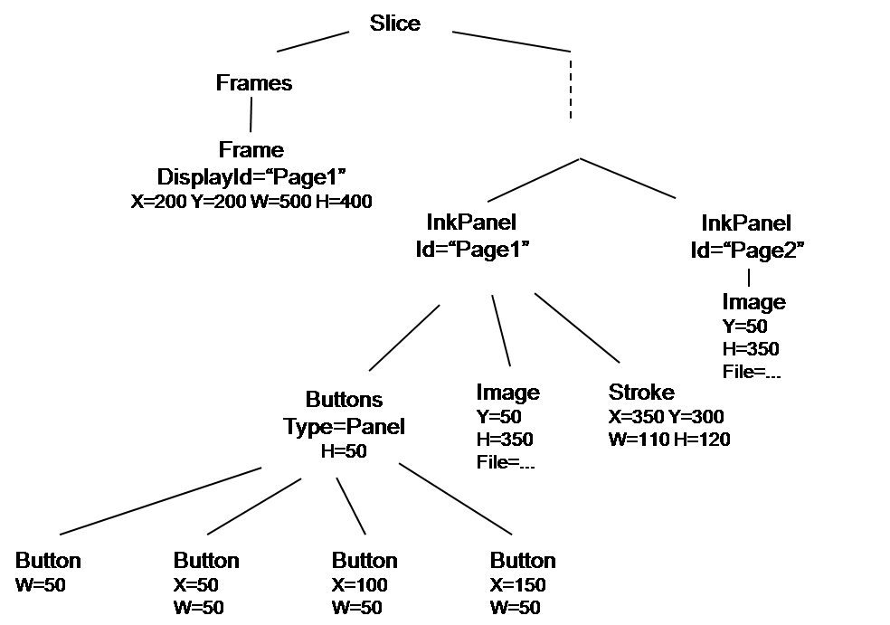
So, what do scripts do when they're invoked? For the most part, all they can do is change the tree. Suppose the button with the arrow on it does the following: it creates a new page node with the same image as the current page (but nothing else from the current page), and a new Id, and places it next to the current page. After clicking this button, the tree would look like this:
To make this happen, that button node would have an attribute OnClick with the name of a JavaScript function containing these lines:
    thistree = Slice.FindNodeById("Page1")

    newimgnode = thistree.GetChild("Image").Clone()

    newtree = tree("InkPanel", [], [newimgnode])

    newtree["Id"] = CalculateNextId(thistree["Id"])

    tree.GetParent().AppendChild(newtree)
where CalculateNextId, which is not shown, would calculate "Page2" from "Page1" (or, more generally, "Page(n+1)" from "Page(n)"). FindNodeById finds the node with that Id (Id's must be unique within a tree). The "tree" operation creates a tree with the given name (InkPanel in this case), and with given attributes (none given here) and subtrees (the copy of the Image node). The other operations are hopefully self-explanatory.
Thus, writing extensions requires knowing (1) the structure of the tree, and (2) the set of available tree operations. The tree structure varies according to the specific application (see the technical documentation for each application). The tree operations are documented in the scripting guide.
The network model is very simple. The underlying system registers users and provides a mechanism to send messages to any subset of users. When a message is sent, the system hands the message to the message handler for that application. After that, message interpretation is up to the application. Messages are trees, so that one machine can send another an entire subtree to be placed into the receiver's tree. For example, in the networked lecture application, the instructor might start the class by sending every student the entire lecture tree. The message can give an indication of where the subtree is to be placed, using a protocol specific to that application; e.g. in the lecture application, an ink stroke should be accompanied by an indication of the page it should go on, where "page," you will recall, is a notion meaningful to the lecture application but not to the core system.
To see how these ideas can be used to create Tablet PC applications, we consider two scenarios, the single-user and networked lecture applications. (This is just a general discussion; documentation for each app gives the specifics.)
When we use the term "application," we are referring to a "stand-alone" application, involving an initial tree (represented externally in XML) and a set of scripts. A "feature" refers to something added to an existing application; there is no clear distinction between the application itself and its features, but we think of a "feature" as something that is not essential to the application, and goes beyond the basic requirements of the application. By an "extension" we mean any functionality involving scripts.
The single-user lecture application is what a lecturer with a Tablet PC would use if she were teaching in a classroom in which the students did not have their own Tablet PCs. In appearance, this application contains a collection of buttons for things like changing pen types and color, moving between pages, inserting a blank page, etc. Here is how we might implement this application (actually, this is exactly how we did implement it): All information about the lecture is contained in a subtree with root named Lecture. That node has three children, all Panel nodes: BottomToolBar, VerticalToolBar, and Slides. The first two contain buttons, and the third contains InkPanel nodes (the separate slides of the presentation):
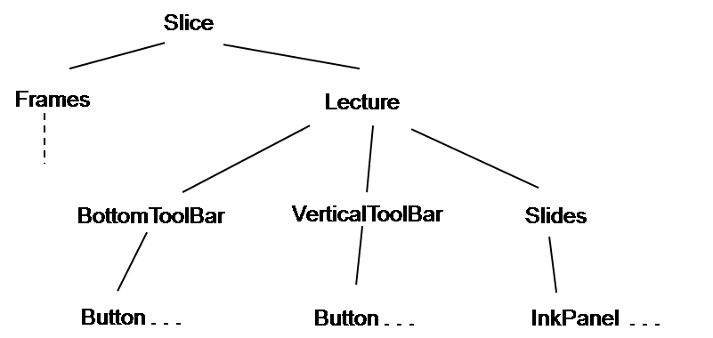
There is one Frame node under the Frames node, whose DisplayId point to the Lecture node. (Specifically, the Frame node has DisplayId=Lecture and the Lecture node has Id=Lecture.) Each InkPanel represents a slide in the presentation, and the order of the list of InkPanels is their order in the presentation. Of course, only one of the InkPanels is the current one, and this is determined by a simple test: Exactly one InkPanel has attribute Visible=True, and the other have Visible=False. (Visible is a built-in attribute that tells the underlying display code whether or not to display that node and its children; since a node that has no Visible attribute will be displayed, it is important that all InkPanels but one have Visible=False.)
Consider the action of moving to the next page. This involves these steps: (1) Find the current node; this is done by using the FindChildByAttribute function to look for the child of the Slides node that has Visible=True. (2) Find the right sibling of this node, if any, using the NextChild function. (3) If the right sibling doesn't exist (its value is null), do nothing more. (4) If the right sibling does exist, then set the Visible attribute of the current node to False (using SetAttribute) and of the sibling to True. Voila. (The reader may observe that there is an inefficiency in this process, in that every page switch involves a linear search through all the Slides to find the visible one. If this were a problem - we haven't found it to be one, since presentations rarely exceed fifty slides - then the structure could be changed to store the current page number in the Lecture or Slides node; then finding the next page would involve an increment operation and a (constant-time) array lookup, using the operation node.GetChild(n).)
As another quick example, suppose we want to make a copy of the current slide. (For example, an instructor working on an example may want to modify it while retaining the previous version, so that the lecture would show the sequence of actions.) Here are the steps: (1) Find the current node as above. (2) Make a copy of it (and its children) using the Clone operation. (3) Insert it after the current node (InsertAfter). (4) Set the Visible attribute of the current node to False. The Visible attribute of the copy is already True, since it is a copy. (This means that there are temporarily two visible InkPanels, but that is harmless.)
Consider now the networked lecture application. In one version of this application - the "WIPTE demo" - ink strokes made by the lecturer are instantly transmitted to all students. As mentioned above, this is done by sending a message containing the "location" of the new ink stroke, and the tree node representing the stroke. "Location" is an application-specific notion. In this case, ink strokes go at the top level of the InkPanel subtree (i.e. as children of the InkPanel node), so the only location that needs to be transmitted is the page number. (Other applications, such as the 242 code review application, may not have any notion of "pages," so some other protocol for determining locations has to be devised by the application writer.) There is a subtlety here, however. It is possible that the student has added a page to his own lecture notes, thereby changing the page numbering, with the effect that the lecturer's ink stroke ends up on the wrong page. Thus, the page numbering scheme must distinguish between the instructor's page numbers and the student's page numbers. There is no special difficulty in doing this - just add an Author attribute to each page - but it gives some indication of how networking complicates matters.
Another complication in the networking application is that different users have different roles. The instructor's ink is automatically sent to the students' computers, but not vice versa. There can be other roles beyond Instructor and Student. The TA, for example, might see student questions that the instructor would not (to avoid distracting the instructor). The Display is a virtual participant whose state contains just the things the students should see on the classroom projector, and not the things the instructor wants to keep to himself. For example, the instructor might occasionally want to peek, electronically, at a student's screen, but not show it to the other students. Roles can be stored in the tree as attributes and scripts can look at those attributes; alternatively, the various script attributes could be altered so that each role has its own set of JavaScript functions. The networking code allows messages to be sent to a subset of all connected users, based on their roles.